
Rebuild, Direct Drive, Build Plate and Tech Upgrades
TPU Action – Upgrade Process
Max Neo Upgrades: The Upgrade Process, Part of the TPU Action Series
Now, let’s discuss the Creality Max Neo 3D Printer Upgrade – unboxing, teardown, install of upgrade parts. Our goal is to improve TPU scalability and production quality. As a side note, we received a refurbished Max Neo and will cover the PETG settings and troubleshooting process in our next article.
We have already discussed the reasons for upgrading the parts and quality benefits it brings. We have purchased the necessary parts for the updates to increase our success rates. Now, let’s move on to the physical upgrade.
Unbox Upgrades
Let’s get started, shall we? We have got our boxes and can officially begin the TPU Upgrade process. All parts have been unboxed, including the new extruder with direct drive that features an easy-to-install quick connect with locks on the print head. Additionally, we have the rail cart for bolting the extruder to the rail and powering it with the axis motors. Next, we have the new silent motherboard, which is necessary for installing the Creality Sprite Extruder Pro kit. Secondly, we have the new bed plate ready to go. Once the process is complete, we will test the machine first without the upgrade and then with it to ensure everything is printing smoothly.
Unbox Parts, Printer Teardown and Disassembly References
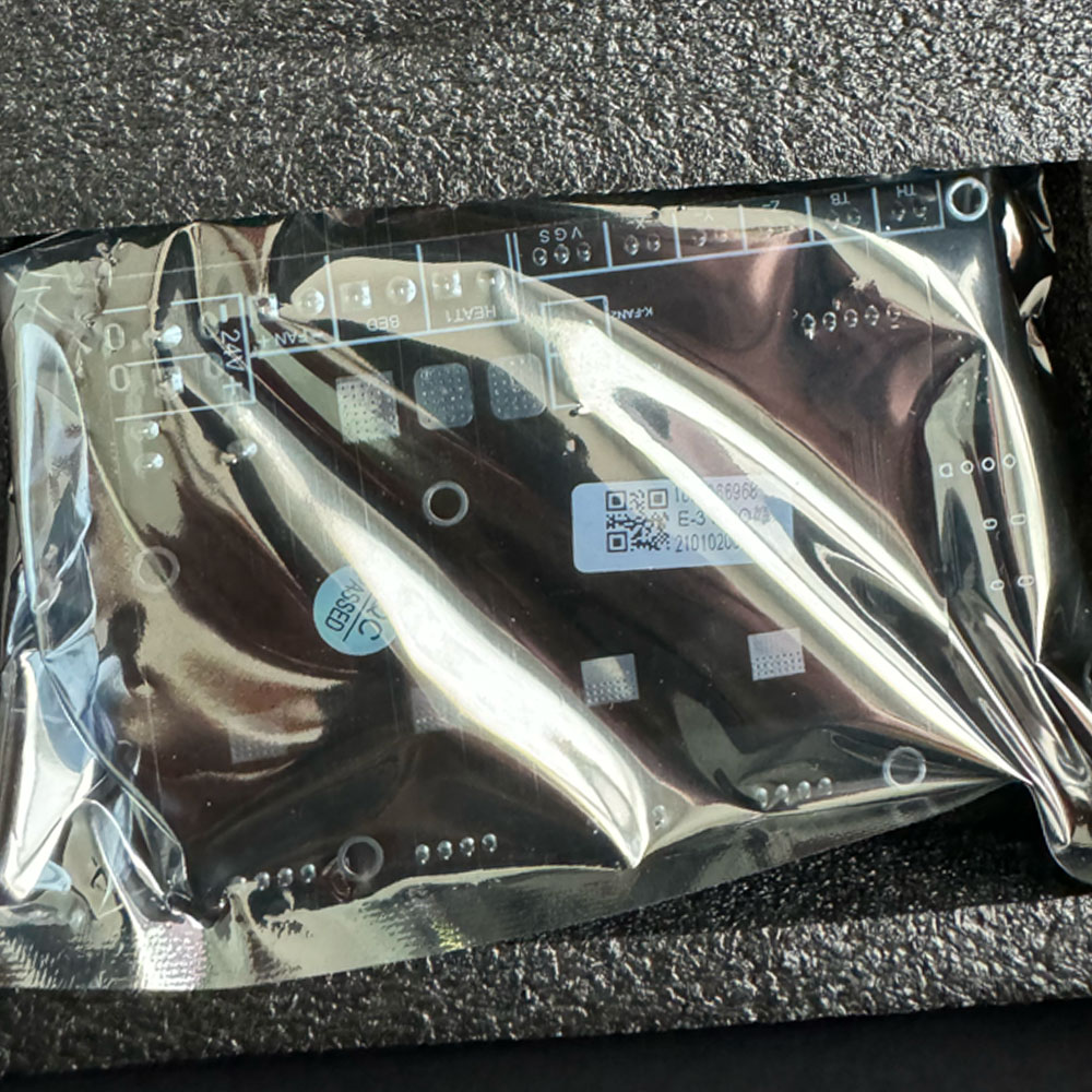
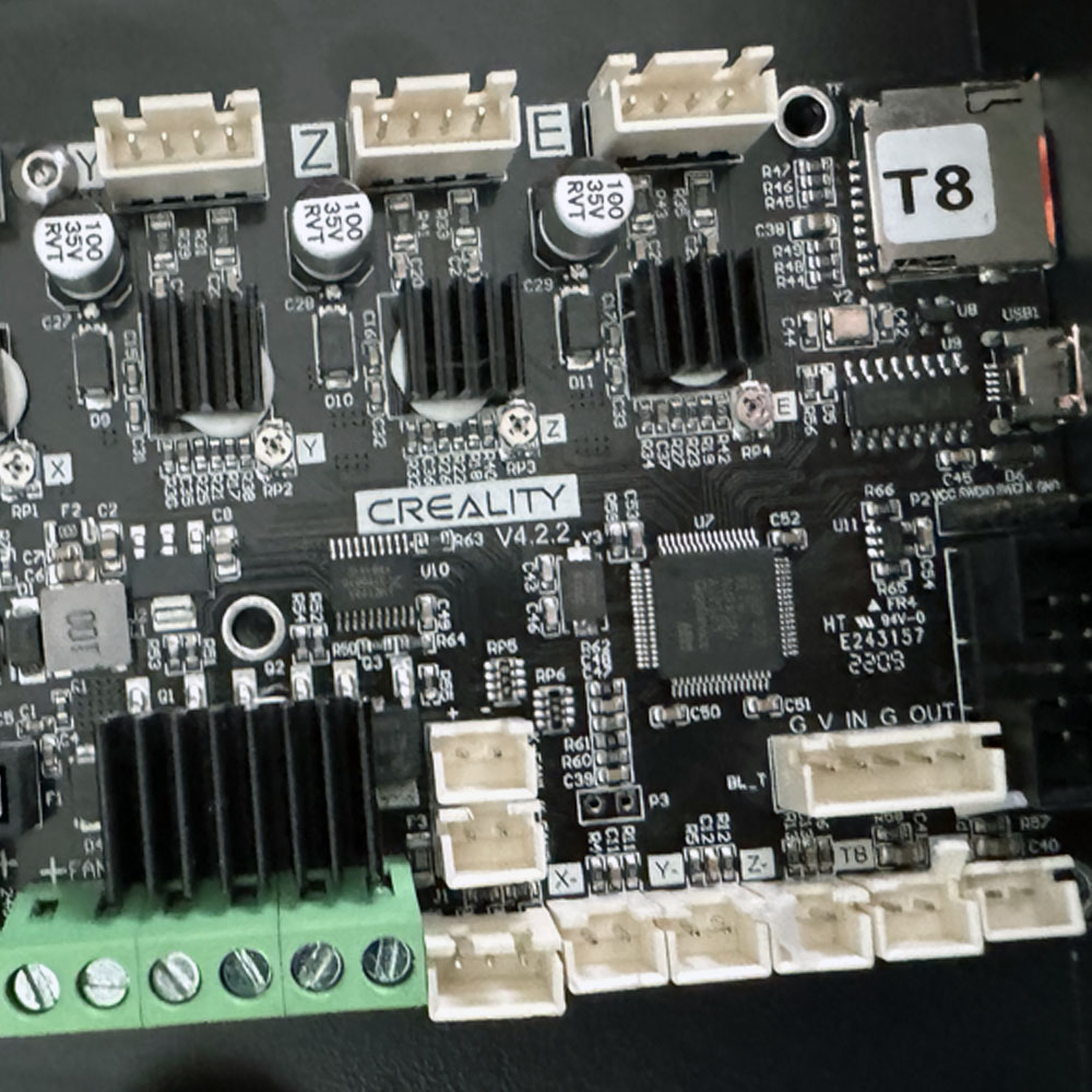
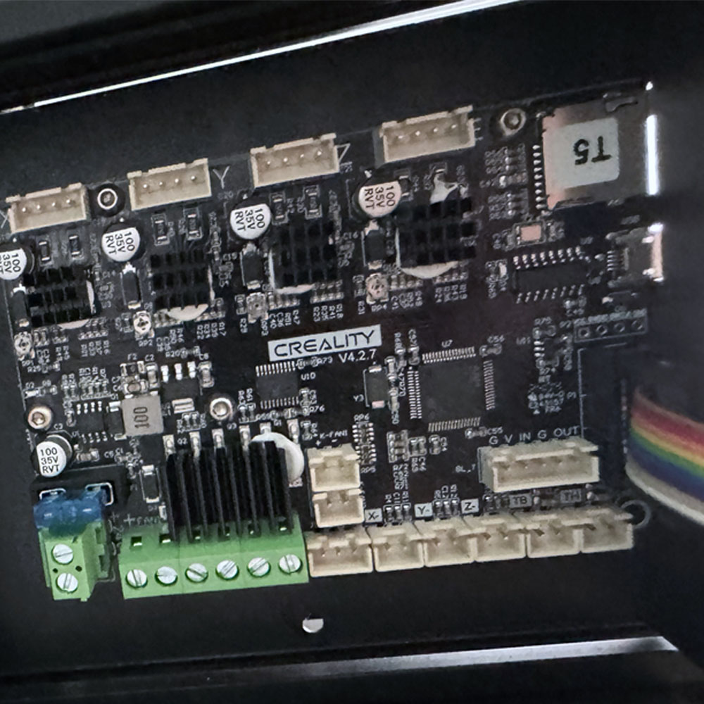
Motherboard v4.2.7
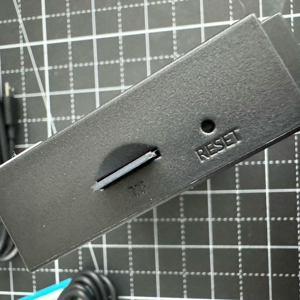
WiFi Box 2.0
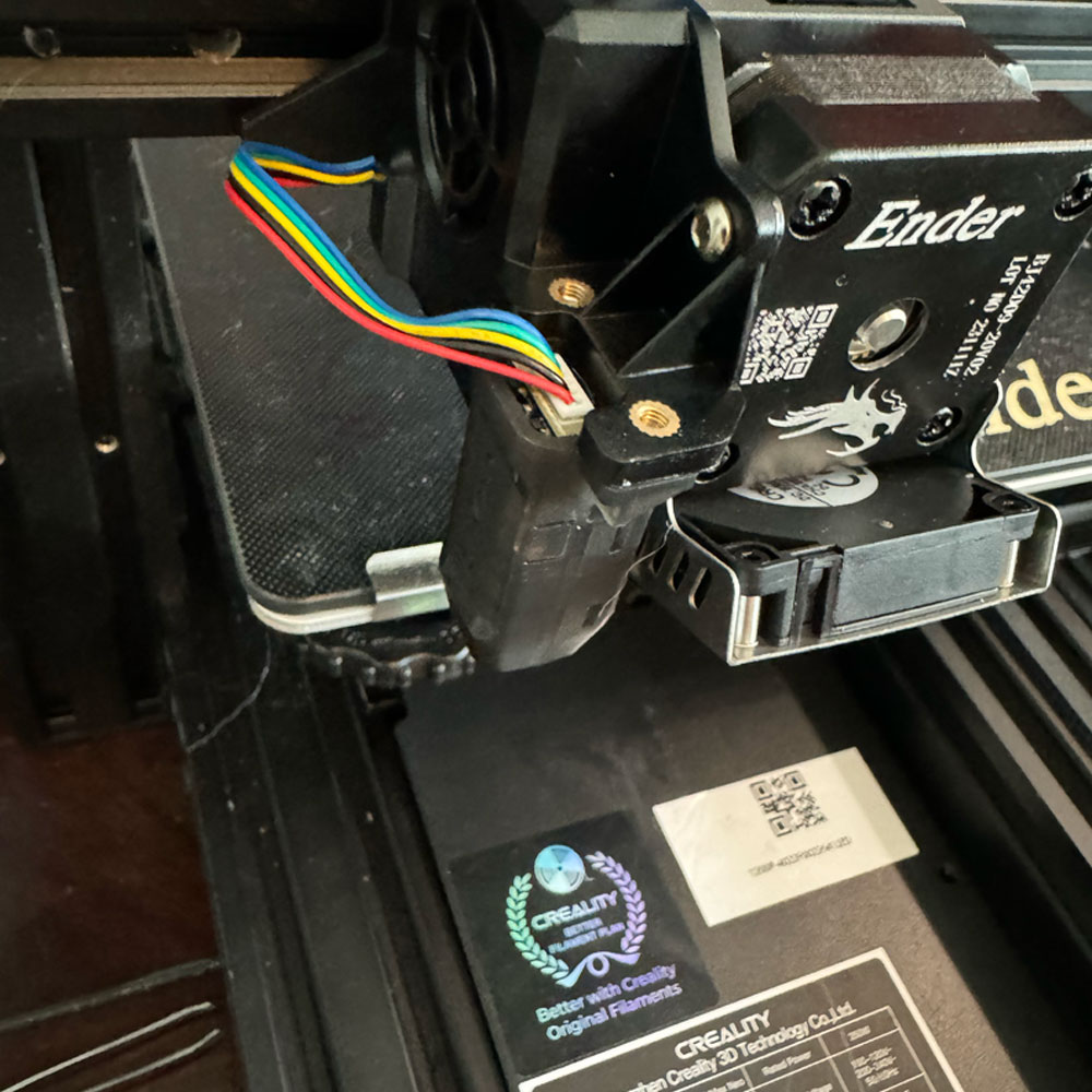
Sprite Extruder Pro Kit
Sprite Extruder Pro
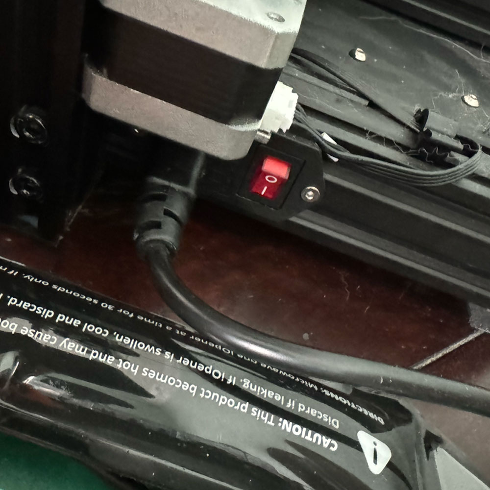
Power Down
Unplug
Prep Screen & Unplug
Disconnect Motors
Starting the TPU upgrade process? Let’s begin by removing all power cords. If you have a Wifi 2.0 Box or Sonic Pad, those should also be powered down and their cords removed. I prefer to start fresh with no cords. Now, we have our tech tools. I will post a link to the shopping list following this post. If you have the original set of tools provided by Creality at purchase, those will work just fine.
Begin Teardown, Be Careful and Take Your Time
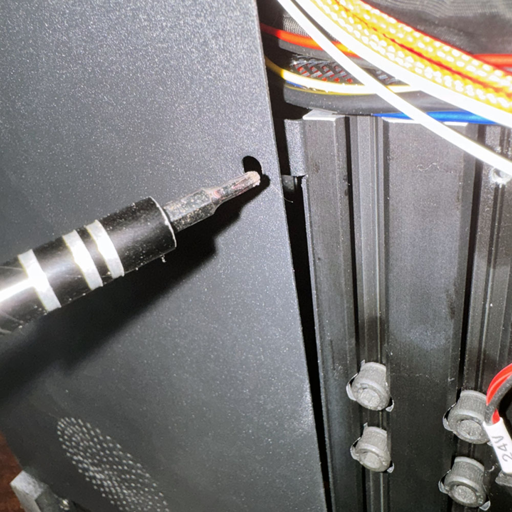
Let’s dismantle the printer by taking apart the extruder and the extruder rail cart. After removing a few bolts, we should have the printing area cleared. It’s worth noting that this particular printer has previously been upgraded making the direct drive easily accessible. For more information on the original direct drive build you can refer to the Ender Teardown, Rebuild – 5 Part Series. In the series, you will see the filament being removed, power cables unclipped, e-touch and cable connections from the extruder to the board, bolts being removed, cart being taken out, and extruder being detached. The printing area should now be free of extruder parts and the rail cart
Look around the 3D printer frame, specifically the drivers, those should be unclipped as well. I also like to disconnect the screen here. There is a clip on the back: the ribbon connector can be unclipped and set aside. Now, gently lift and turn the machine clockwise, placing the machine on its right side or screen side (which has been removed for this exact reason).
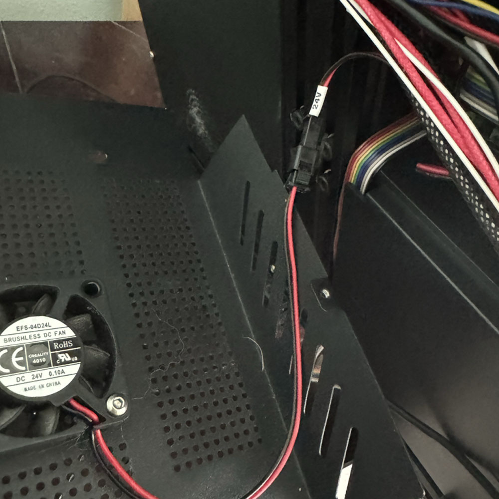
The top screw does not need to be removed here; it is one of 4 or 5 screws that hold the motherboard to the base Start by unscrewing the right-hand side first (motherboard side), being careful to unplug the 0.10 A computer fan clip, and then move on to the left side (power side). Ribbons, cords, and wires of various shades and colors may have shifted around a bit, especially in this case, as the printer was previously upgraded. Therefore, electrical wires or shield tape may be wound tightly. Be gentle with the cover screws, as they will be used again in approximately 15 – 30 minutes.
Unbox and Preparation
Motherboard v4.2.7
WiFi Box 2.0
Sprite Extruder Pro Kit
Sprite Extruder Pro
Power Down
Unplug
Prep Screen & Unplug
Disconnect Motors
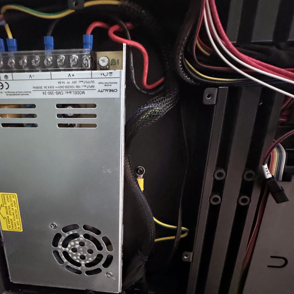
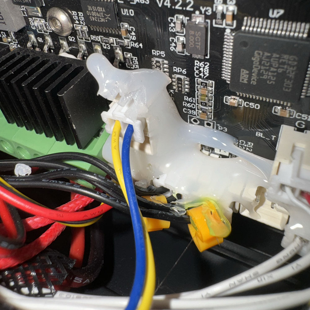
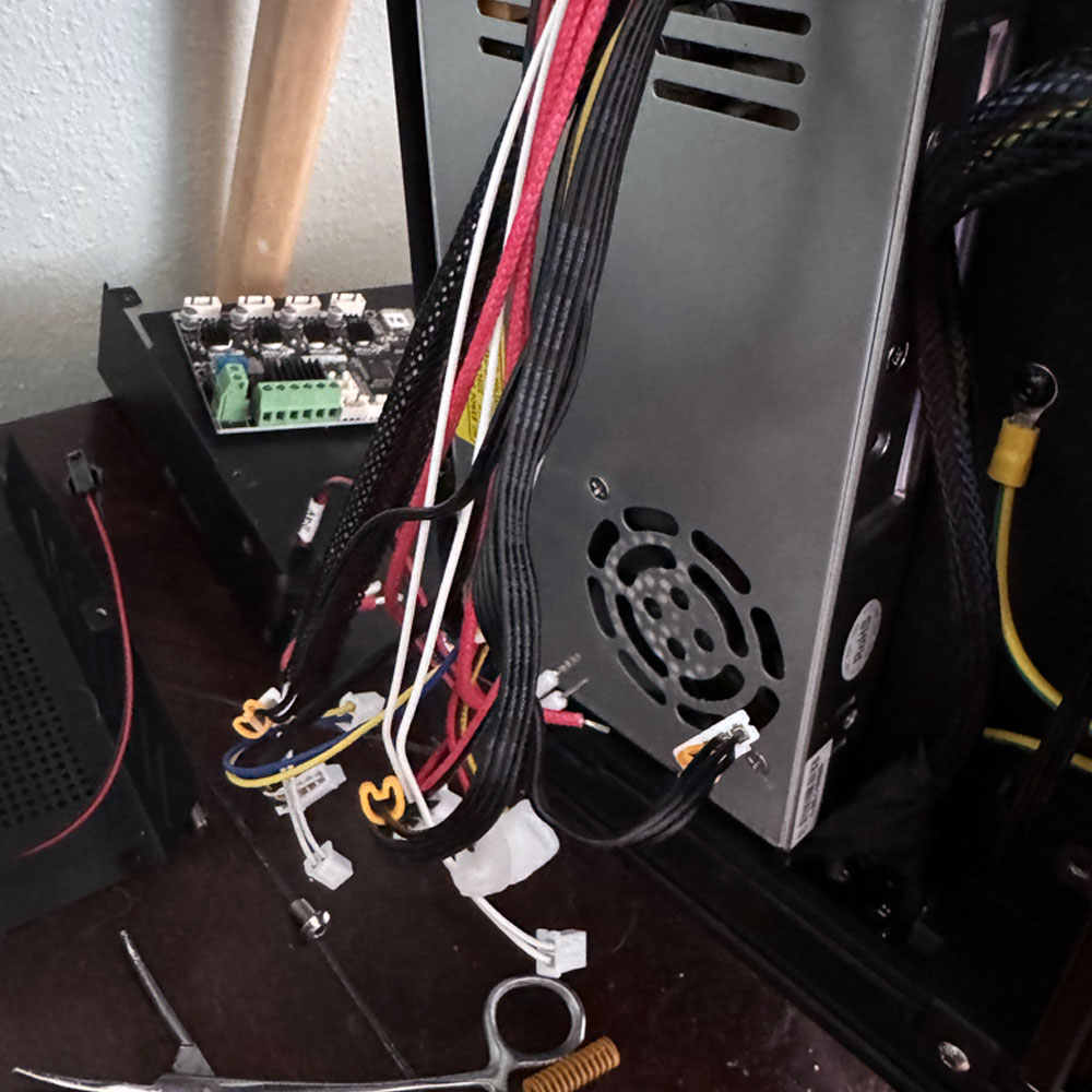
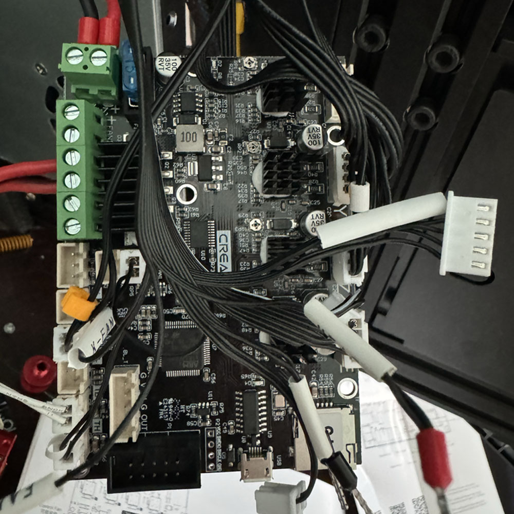
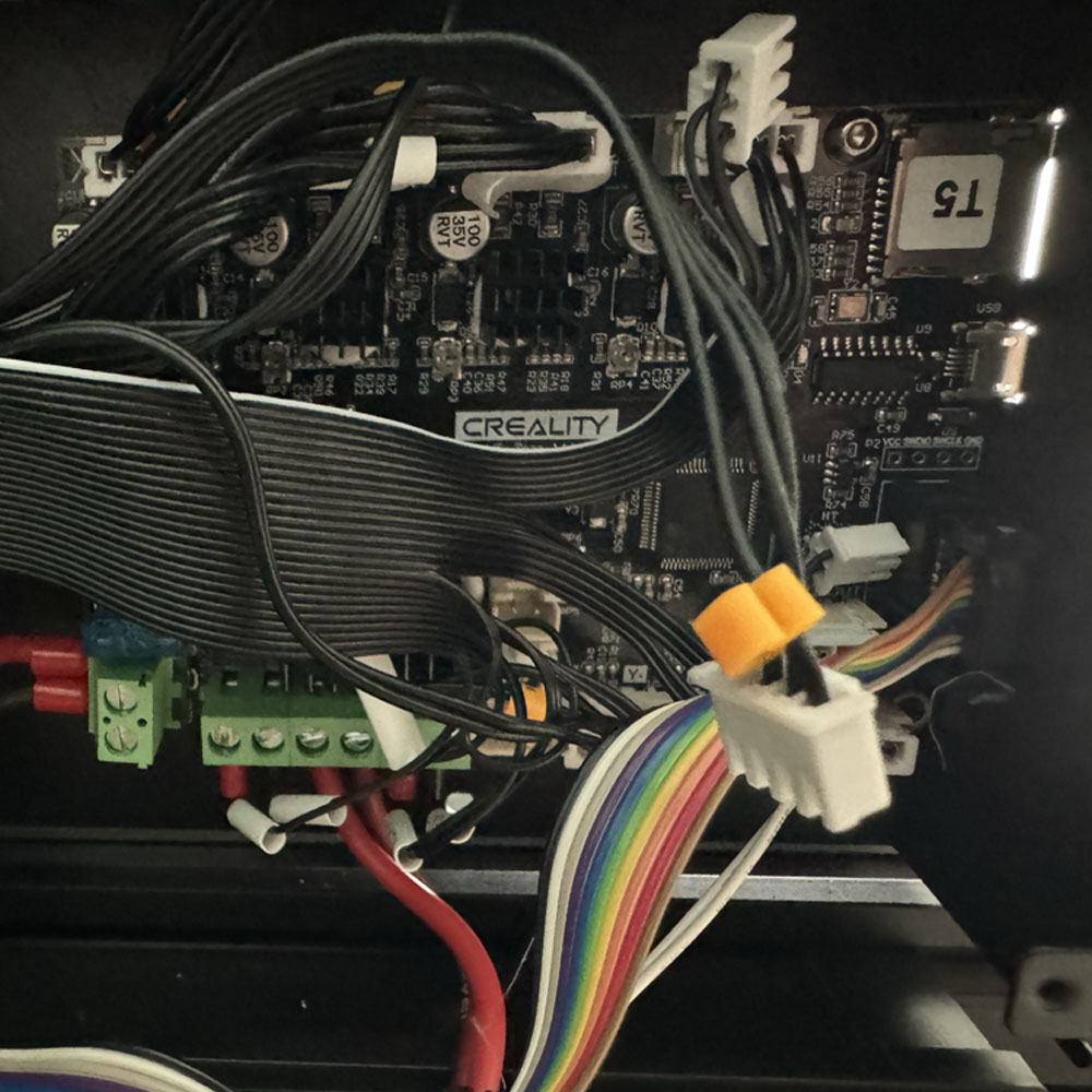
Take a look around, assume if you have tilted the machine clockwise on it’s side by roughly 90 degrees and removed the screws. On the left, we are examining power management, and on the right, control.
Equally important, a visual inspection will reveal hot glue on all or most of the motherboard connectors, depending on the condition of the machine.
If the machine is new or refurbished, hot glue is common, so don’t be alarmed!
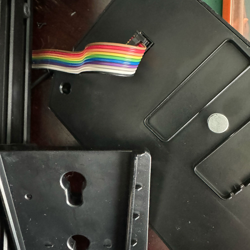
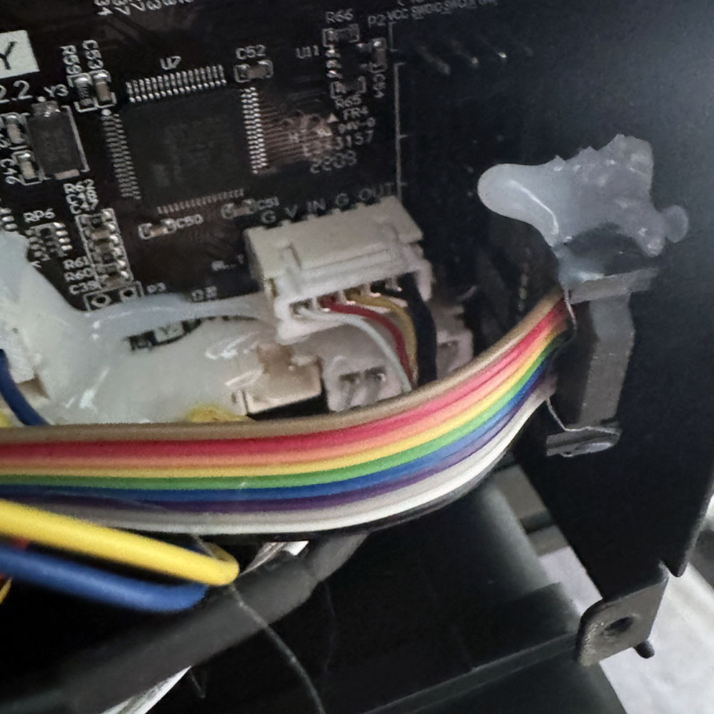
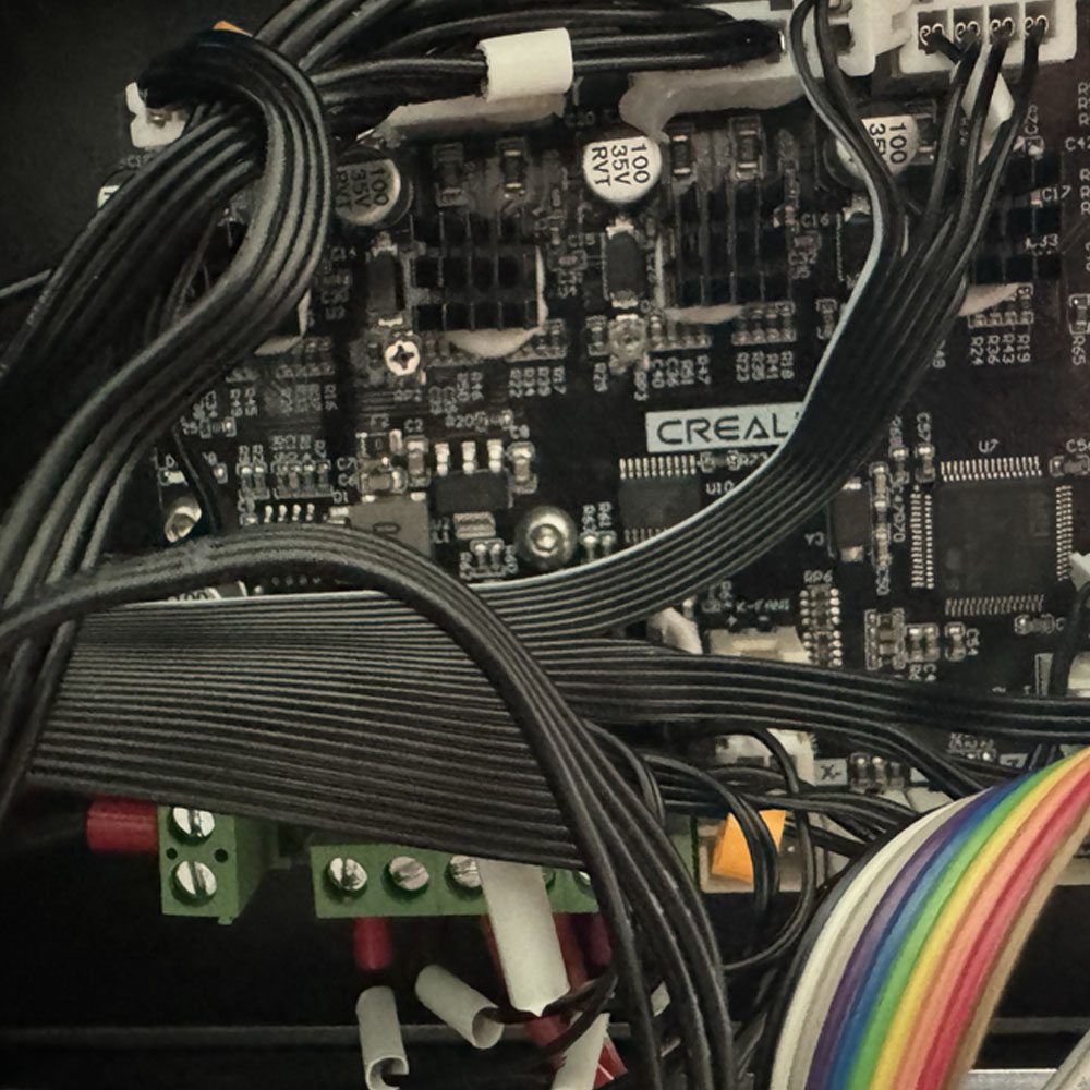
This is to be expected for Creality machines. We will begin removing the glue using a spudger, hemostats and/or gloved hand. In this process, we start from right to left, starting with the screen connector (rainbow ribbon), the top connector marked GV IN G OUT, the mini two-wire connectors (grey and the black axis wires), the fan wires (yellow and blue), and the red, yellow and black harness. Ignore the power wires for now, we will be address those in the third step. Next, we will move to the top of the board to disconnect the X, Y, Z and E black wire harnesses. You’re almost there, you can do this!
Disassemble Extruder and Motherboard
Internal Fan
Unscrew Power Cover
Power Unit
Unscrew Housing
Motherboard
Hot Glue Removal
Start Right-to-left

Disconnect Cables
Fans & Power
Disconnect Power
All Connections
Remove Board
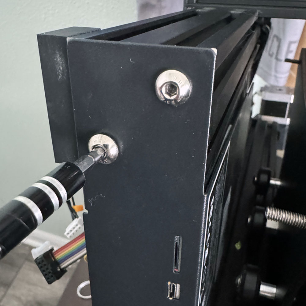
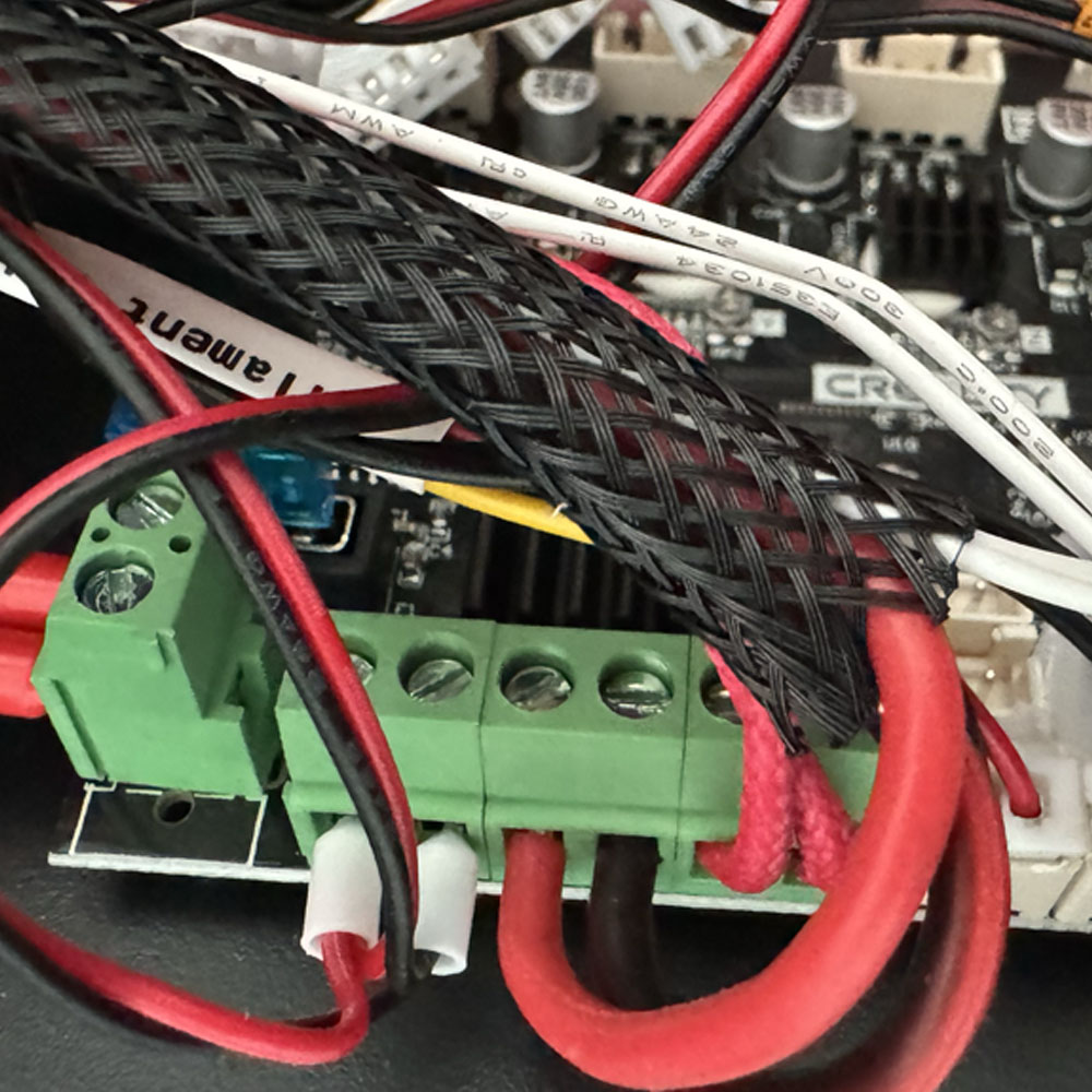
Let’s move on to the green locks next. Using a flat head screwdriver, start from right to left to unscrew and remove the red and black wires. Voila! We are now 50% complete. The glue removal process usually takes the longest, making it challenging to navigate the board space. Let’s unscrew the board from the frame (unscrew the two bolts on the front), leaving the last screw on the top, removing the top from the frame. Unscrew the motherboard and set it aside for safekeeping or for use in another refurbished printer in the future. Take a moment to check around the frame, organize the screws and bolts (I recommend using a piece of paper and a Sharpie). Draw a box label it, and tape the hardware screws securely.
Motherboard and Extruder Installation
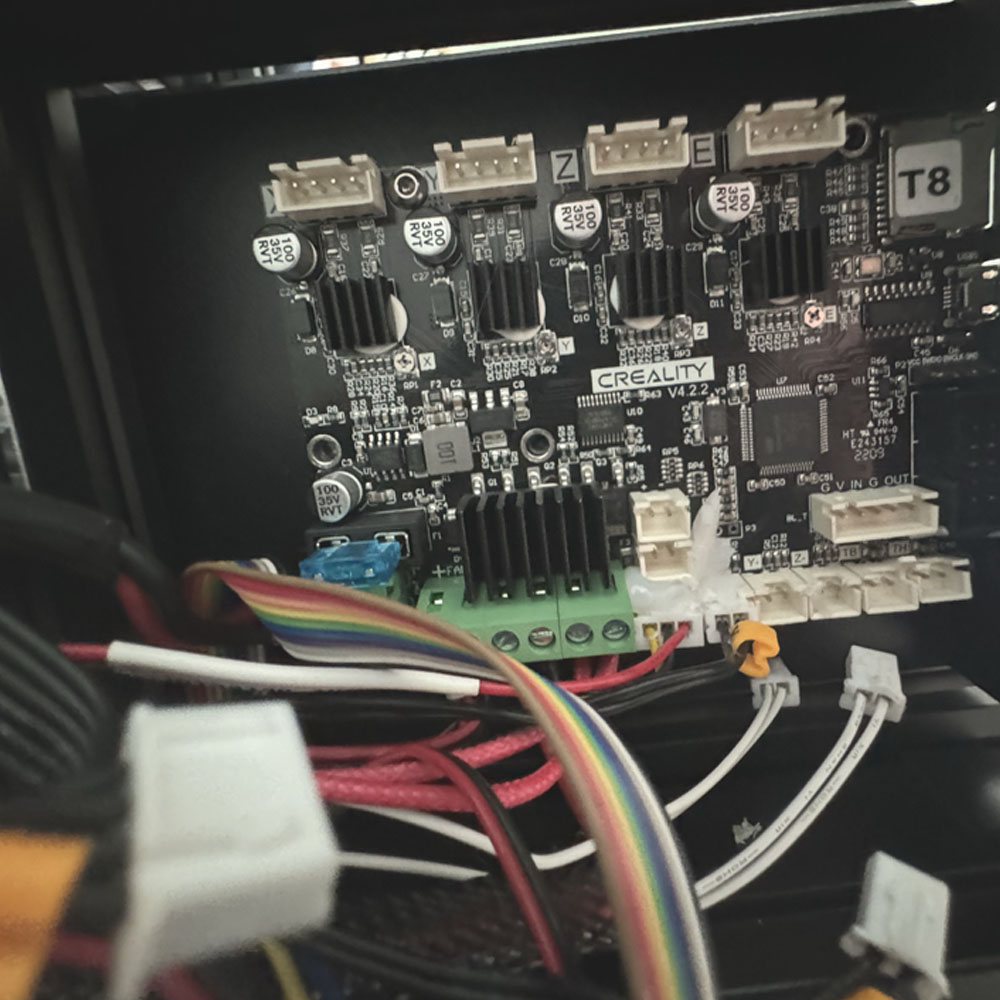
Straightaway, let’s start by removing the new motherboard from its package, if you have not already done so, and placing it into the motherboard (control) space. Additionally, make sure to safely connect the USB and MicroSD connectors on the board first, then align the board with the appropriate screw mounts on the board. Once the screws are in place, the board should sit firmly in place, secured and ready to go!
Reassemble 3D Printer, Upgrade Reference
Attach New Board
Left-to-right
+ and –
Fans and Motors
Upper Cables
Seat Cables
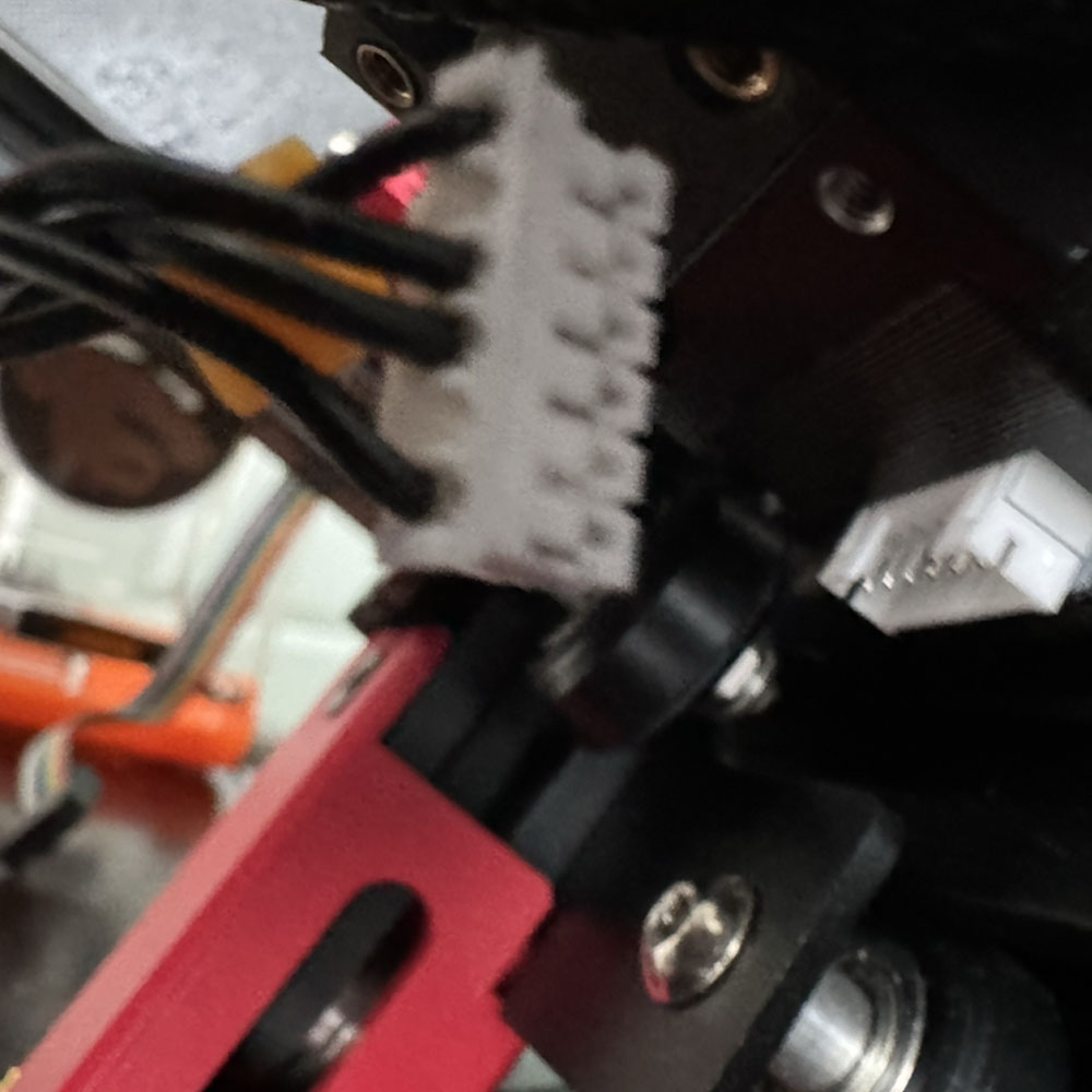
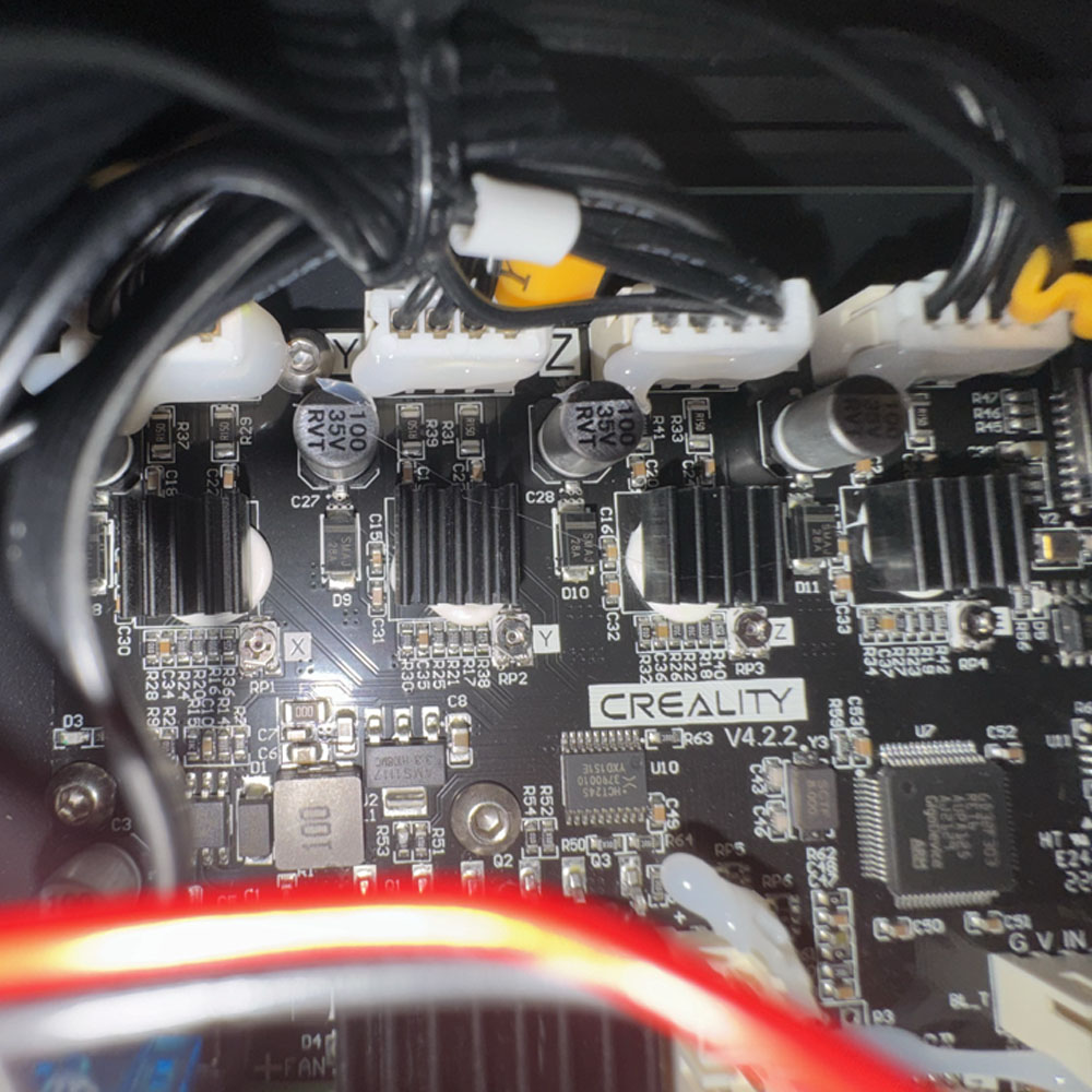
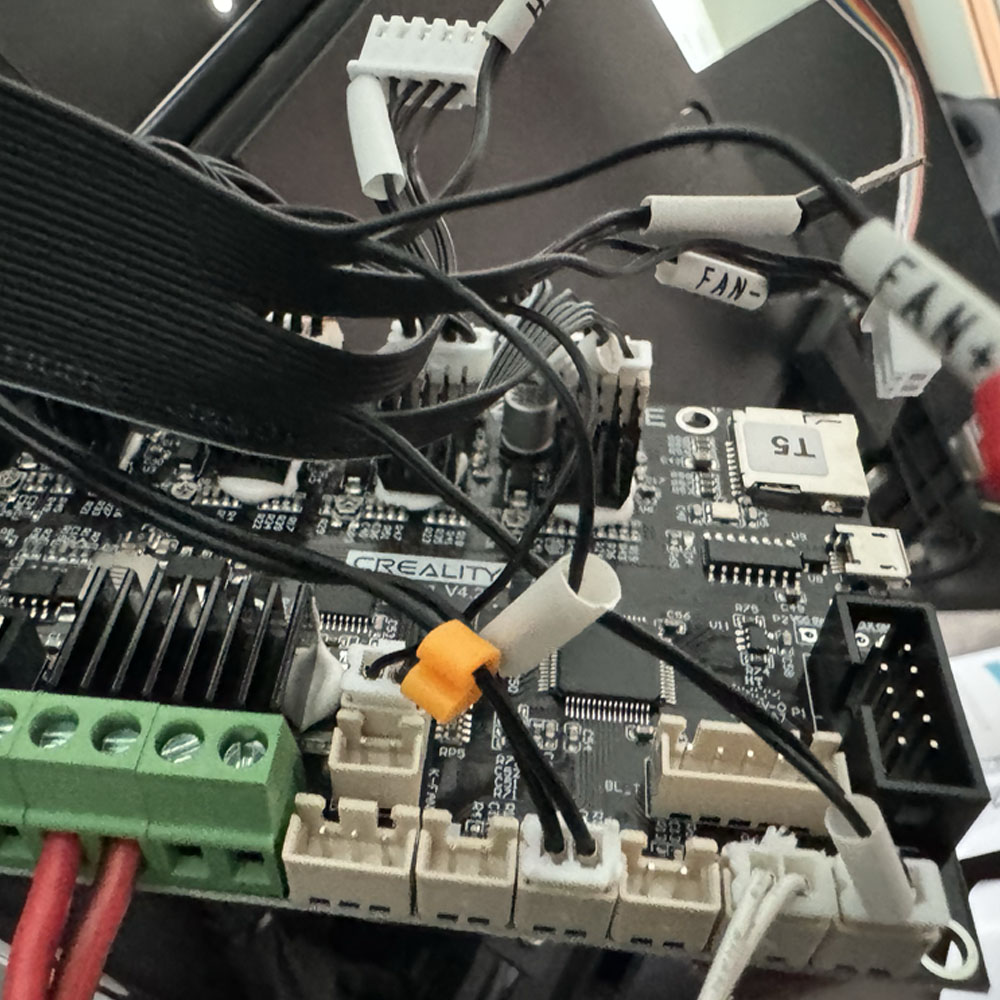
Okay, in reverse, the TPU Upgrade process continues with the new Sprite Extruder raw wire ends. Start by securing the green motherboard locks first, moving from left to right. The power from the power unit should be on the side of the board, with alternative red/back wires. Make sure to read the labels to ensure the correct landing spot for those power wires. Next, connect the yellow/blue fan and the red, yellow, and black wires just below the fan connector. Moving right replace the x-, y- , z-, TB, TH, and GV IN G OUT connections. Now, connect the screen ribbon. Double-check all fittings and secure the green locks on the board to ensure a snug fit.
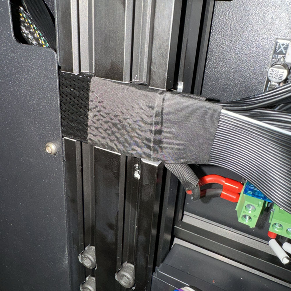
Finally, when working on the motherboard, let’s replace the screws on the power unit side carefully. Run the wires through the notched metal railing and secure the front bolts for the control cover, bottom screws, and the top screws. This is a critical area where you must exercise caution, as the cables can easily break. Take your time here.
Post Installation Checks, Screws, Belts and More
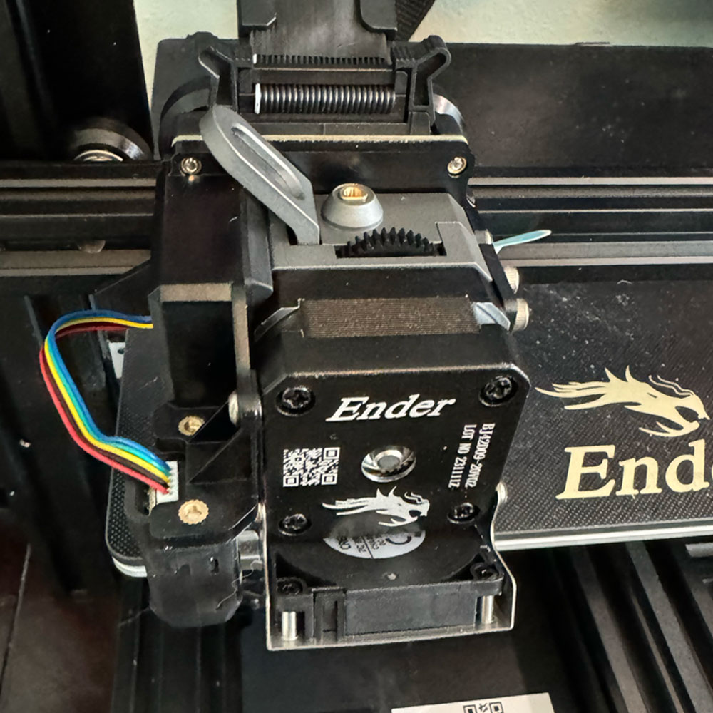
Continuing on, secure the Pro Extruder Kit. Lift, turn, and place the printer in its center. All wires, ribbons and connectors are ready for the new drive. Next, install the extruder and fit it to the assembly cart. Thirdly, connect the e-touch ribbon cable, seat the cable so that is snug. Fourthly, seat the red hot wire creating a connection between the hot end and the extruder. It may have a tight fit, so now is the time to place the wire while the extruder is loose on the cart. Secure the extruder to the cart mounting point by placing the screws and tightening them down. Moreover, ensure a secure and tight connection, firmly setting the drive in place!
Next, if you machine has an E-touch, screw it to the provided mounting hardware. Ensure a good fit by checking the orientation and making sure the extruder card fits snug on the rail. Securely attach the axis cables or rubber power drive belts. The belts slides into place on the backside of the assembly cart). This should be loose from the if dismantling process. Firmly, attach axis cables, or rubber power drive belts. Undoubtedly, the belts slide into place (two slots cut out on the assembly cart) on the backside, if you remember during the teardown process. Next, loosen the X/Y axis drive belts using the red knobs, one on the front and the other on the right side. Now, tighten those knobs by turning them clockwise to apply tension to the belts and cart.
Extruder, Power On and Level
Seat Extruder
Power On
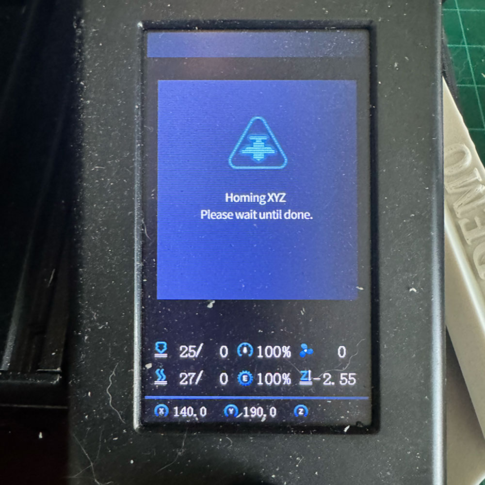
Hone & Level
Replace drive connectors, which are key for stable linear and vertical movement. Reference tags will indicate connectors for controlling the x and y drive motors. Install the extruder ribbon by tucking it behind the two black plastic static tabs located just above the connector saddle and ribbon locks.
Now the real test begins… the TPU Upgrade process continues to the next round! The series progresses, read more about TPU Post Processing or go back to the beginning with TPU Action. Finally, we will cover the initial settings, slicer, accessories and final settings in the next installment, so stick around. If you’re new to the series you can revisit upgrade parts on our affiliate shopping area and review pricing, upgraded hardware reviews, accessories and filament essential for this build. Alternatively, you can skip ahead, review article upgrade parts and accessories in the series opening.