Wiring reference materials. Reference materials for the ADT Panel and the AC Gilbert American Flyer trains. Good practice to maintain wiring references.

ADT Wiring

ADT WiringADT Touch

Let’s Rewire the ADT Touch Screen

ADT Security System Control Panel

Lab Work – ADT Control Unit

Archived for Future Reference, ADT Wiring Touch Panel. Need help? Just remember to always take a quick picture for historical backup value.

It’s time to cut, rewire and reinstall. This article will serve as a reference for ADT installations, specifically for the new generation touch panels. Think of it as a guide on how to reinstall touch panel wires post-improvement. Additionally, if this serves as a reference for those who may need help with future wiring or rewiring exercises, a picture can be invaluable. It’s pretty simple: focus on the main wire for power. Since is wireless system, there aren’t really any other wires. First and foremost, we encountered a minor issue with out ADT Touchscreen security system and needed to deactivate the system.

Secondly, we needed to relocate the system from the frontside of the wall to the backside. Sounds easy, right? Ultimately, it didn’t take long to move the screen from the front side to the back, which happened to be the interior actually the backside was the interior of a vented closet. The only note here, don’t forget which one is + (positive) and which one is – (negative), 50/50 shot on this.

Ready to Reinstall

There is no way to fail. Ideally, you’ll just move the unit, pick a new spot and wire up the wireless control panel. The problem comes in a small form, battery on the underside of the unit, and two connections. We have a red, black and white wire connector and the two lead wires are black and red which read (GND) and +9v. There is truly, only one way to push in the connector, while the black and red wires should be easy, Red Hot +, Black Ground -. ADT wiring goes like this find a new spot, screw in the touchpad screws, clean the wires, clip and prep, small screwdriver to push in the wires black for GND and Red for +9v. Push on the control panel. 

Hey, before you go, this article is similar to our calculator work… a few screws, a new battery, a solder or two and done. Got to keep these old electronics running as intended. We will keep the quick electronics fixes coming! Check back for more lab work.

Leave us a comment below, cheers.

Calc Rework

Let’s Get A Fix In Place For This Calculator

Calc Rework,  Fix, Rework and Repair

Calculator Work, Fixing the old calculator

Lab Work – Fix the Calc, Calc Rework

Broken Calculator, Let’s fix it. Don’t want to keep this little piggy waiting!

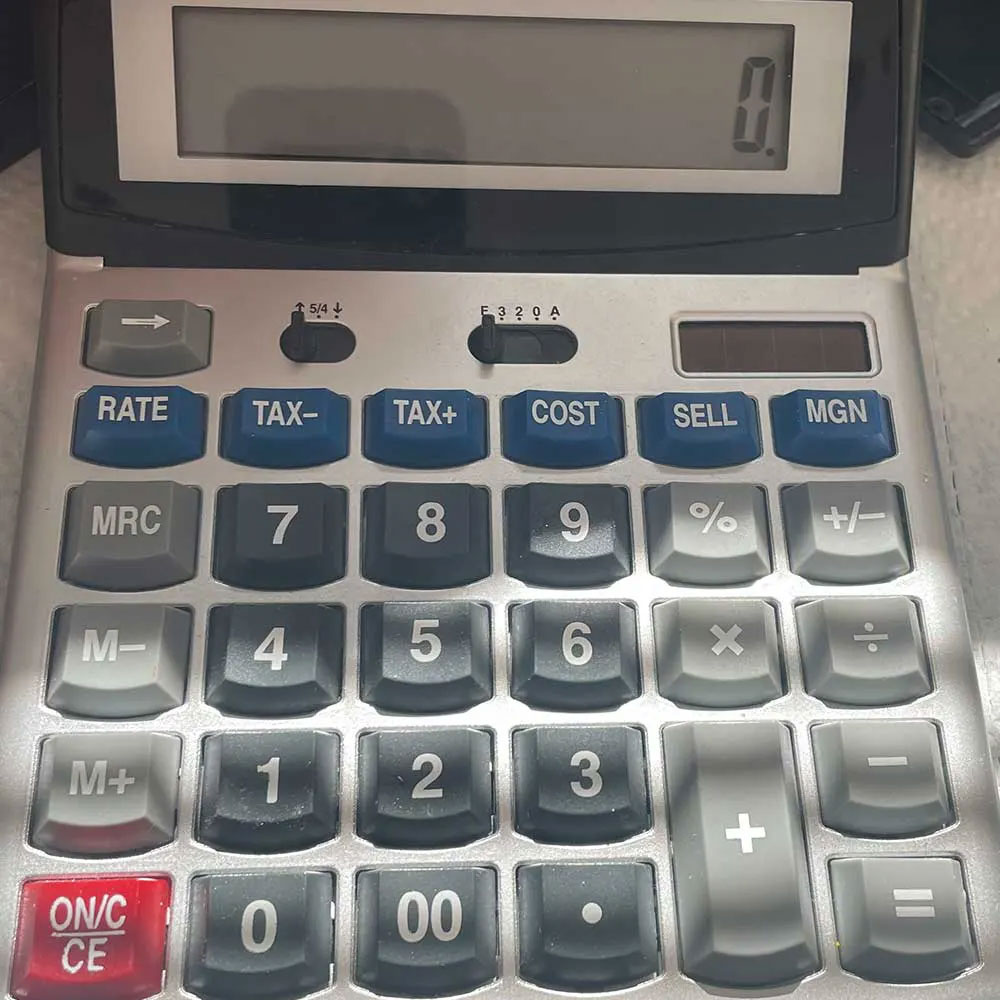
Calc rework started a few months ago. We’ll keep this post short and brief… This calculator showed up on the work bench with minor issues. Connections all busted, it looks like an animal, a vacuum, nature or something was able to get to the calculator and internals.

Anyway, after fixing a few connections and installing a new CR battery, this little piggy is like new again! Easy work, no major issues with the main board, keys, case or display. Quick fix.

Calculator Fix
Battery/Resolder

Resolder

Look Here

Look Here

Lastly, I decided to keep little ‘piglet’ sticker on the old calculator because it gives it a new look. It’s a great office calculator with big keys and a large display, making it easier to use than those tiny digital smartphone keys. I reminds me of the  old Printing Calculators, kind of like this Sharp Printing Calc. It brings back memories of my parents having used one around the house when I was a child. If you enjoy reading repair articles, consider learning more about robots, remotes, drones, and computers. Wiring guides like this ADT Touch Screen quick reference, keep this handy for future needs, power outages or battery replacement. Or, you might be interested in the Nano Whisk Fix, the M1 MBP Repair, or the latest Dolphin Pool Robot Fix. Feel free to leave a comment below and let us know your thoughts!

ReFit EMAX FC

Cut, Fit & Refit

EMAX THS & Flight Controller Board

EMAX Cut, Fit and Refit

Lab Work – EMAX Flight Controller

ReFit EMAX FC

I thought we could revisit the EMAX FC repair on the EMAX THS. I’ve want to follow up on the previous post, focusing more on the specific, showing the repair process and refitting the EMAX FC. Along the way, I’ll share additional photos of the process as well (in case you come across this article and are in a similar situation with a failing FC). Let’s cover the entire process from start to finish – disassembly process, cutting soldering, and test flight. Once again, soldering/replacing the EMAX AIO FC. Enjoy the photos.

Drone Repair Photos
New Parts

New Parts

THS

THs

EMAX FC

EMAX FC

Drone Frame

Drone Frame

Add Connections

Add Connections

Reattach Power

Reattach Power

Once you have all the parts, fitted, soldered and ready for flight, we will need to configure the FC. Rest, bind, configure and fly, in that order. Check out the EMAX FC and BetaFlight post for more information. You can also learn more about the repair, configuration process and in-flight troubleshooting. If you are having troubles, log into the EMAX Support Portal for assistance with your EMAX products. Lastly, I want to reiterate the steps to fix the FC – Support EMAX THS, remove EMAX FC screws from the Drone PC frame, Cut/Add Connection to Board, Re-Attach New Power Connector with the Battery Carrier”. Time has  moved on since the original post, I wanted to share other Emax content where applicable. If you’re looking for Emax content,  give these a shot (in reverse order from this postings date) – Emax Fix Part 1 and Part 2, Quadcopter Rewire, and the TinyHawk 2

As usual leave a comment below, let us know what you’re thinking?

AF 312 Wiring Schema

AdNeSC  AC Gilbert Model Trains – The American Flyer Series

American Flyer Wiring Schema

AF 312 Wiring Schema - Archived American Flyer Locomotive Wiring

Materials – AC Gilbert Wiring Schema

Rewire – AF 312, with the AF 312 Wiring Schema

I thought this might come in handy for those of you out there, tinkering and wrenching with old model trains, trying to keep our historic, scale models running smoothly. I recently, needed to rewire a 50’s AF 312 Locomotive and Tinder (using the AF 312 Wiring Schema). Also, for future reference, two other models are included the diagrammatic illustration.

Drone Accessories
train truck wheels2

Wheels

train electronic, re-solder

Re-solder Power

The teardown effort went smoothly, with only a little trouble encountered with the tinder card. Resoldering the burnt wires wasn’t a pleasant task. However after swapping in some new wires, fresh resin, and solder, we were back in business. We cleaned out the tinder cart, removing any debris, paint, and oil deposits. The same care was taken with the wheel set, ensuring the original parts ran as they should. This effort aims at restoring and bringing the model trains back to life.

AC Gilbert Schema Diagram

Next, a similar rewire requiring coils is needed for this locomotive, but it does not have those parts. Those items seem to be missing at this point, causing a wiring and parts issue. They appear to be charging coils and connections on the circuitboard, solidifying the connection underneath the locomotive’s body. Unfortunately, this train seems to be missing parts, possibly due to age, wear or simply being lost. Unfortunately, these models need replacement parts for an aging model locomotive set so that this train can ride the rails consistently. 

The rewire challenge is straight-forward, but be prepared to face challenges. Preparation is essential! Check back soon, to see if we can locate the required pieces. In the meantime, visit an AC Gilbert American Flyer train website – www.thegilbertgallery.org that cover s-scale trains, including the #336 Union Pacific Northern and the #293 New Haven Pacific locomotives which are similar to the train we are refurbishing (AF 312 Wiring Schema). Feel free to leave a comment below and let us know your thoughts!